Yu-Shen Ho A UX/UI Designer Portfolio

Fiber Network Management: A User-Friendly Circuit Editing Tool for GIS Systems

Brief

Feb 2022. More and more users have reported difficulty managing their fiber network, especially the circuit data on our platform. They usually need to contact the support team to help them make changes. This project aimed to add a new circuit editing tool that allows users to edit their saved data. 

Goals

  • Build a simpler and flexible experience for users to edit fiber network paths, while preventing users from breaking other data accidentally
  • Improve user control
  • Save users time
  • Reduce the support team’s workload on the circuit related issue

Roles & Responsibilities

  • Led the project
  • Researched user needs and use cases 
  • Discussed the project scope with the product manager
  • Continued workshopping with the product team and engineers to find viable solutions
  • Created high-fidelity mocks and prototypes

Team

Remote team structure with product team and engineers

Timeframe

4 weeks

Understand Problems

Assessing Current Workflow

In the initial phase of the project, I focused on understanding users’ frustrations and pain points through a research sprint. I began by reviewing user feedback tickets from the customer support team and analyzing our existing system workflow.

A key issue I uncovered was that when users needed to edit a path between two points labeled as a circuit, they couldn’t make changes without first deleting the entire path.

This forced them to start over and reconnect the points from scratch, which was both time-consuming and frustrating. Addressing this problem became a priority to improve user experience and efficiency.

Image: Users’ feedback about circuit editing behavior collected by the customer support team. We categorized these tickets from left to right into “Must Solve,” “Consider,” and “New Ideas.

Identify Use Cases

After speaking with five users, the product manager, and customer support members, I identified the main use cases. These conversations revealed key patterns and common challenges users faced. As I analyzed the feedback, it became clear that the use cases could be categorized into three distinct groups, each representing a unique aspect of user needs.
Equipment editing
  • Add equipment
  • Delete equipment
Reroute 
  • Edit existing cable
  • Extend cable
  • Switch fibers
Mix situation
  • Edit existing cable + edit equipment
  • Extend cable + edit equipment

Image: Editing behavior around equipment, cable and fiber.

Scope the Project

After reviewing user feedback and weighing technical limitations alongside our project timeline, we focused on a clear, actionable goal: enabling circuit geometry editing. This was the feature users prioritized most. For more advanced tasks, like automating data or copying splice data, we decided to defer them to future updates, ensuring we delivered what mattered most in the time we had.

Brainstorming

When I started brainstorming ideas of where to initiate the circuit editing action, I had three options.

The left one started from the “Fiber Path” panel. It showed a fiber connection between a start point and an endpoint users picked on the map. By turning on a toggle button, users can edit the circuit connectivity.

The middle one started with the “Edit” panel. It showed circuits related to the equipment. Users can turn on a toggle button to make further edits.

The right one started from the “Edit” Panel as well. When users opened an equipment diagram and hovered over each circuit, it showed a “turn on the circuit editing mode” option. Moreover, I designed a Circuit Editing button on the navigation bar on the top. It would be enabled when users turn on the circuit editing mode.

I chose the right one in the end because it was the most straightforward, easy-to-find, and standalone solution.

Image: Three options to initiate the circuit editing action.

Create Mockups

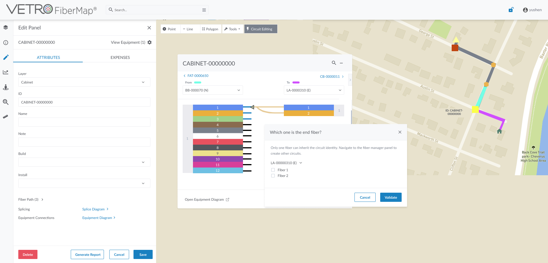
A circuit editing model will open after users click the button in the navigation bar or a circuit in the splice diagram model.

To help our system calculate the right path, for the starting point, or endpoint in a fiber path, users need to fix at least one of them before they make further edits.

There are several options for users to do with the fiber path:

  • Delete the fiber path
  • Find the breakpoint in the affected fiber path
  • Zoom into a certain circuit
  • Edit the circuit
  • Rerun and validate the circuit after they finish the edit

When a circuit hasn’t finished editing and been re-validated, it will be labeled as a work-in-progress status. There is a notification sign showing on the circuit editing tool as well. 

On the report page, users can see unfinished editing fiber paths. Except for the “finding the breakpoint” option, users can engage in the same operations to the fiber paths as in the circuit editing model. These paths will not be shown in the circuit report until they are finalized. 

Design Iterations

After creating the first version of the design, I met with the engineering team to uncover any potential technical constraints. They identified two key challenges that we needed to address.

The first issue we tackled was how to manage circuits containing muxers and demuxers. Allowing users to modify these circuits posed too many challenges, including performance and validation problems. After exploring different solutions, we decided not to allow modifications to circuits with this equipment due to technical constraints. Instead, we added an informational popup to let users know that these circuits couldn’t be edited, even if they activated the circuit editing mode. This approach kept the system stable and helped prevent complications for both users and the platform.

The second challenge we faced involved circuits using splitters. When a splitter was applied, the system struggled to accurately identify which part of the circuit should be validated. This created a risk of misidentifying the circuit or failing to validate the modifications altogether. After some discussion, we realized this was a critical issue, as users could accidentally make changes that would disrupt the network’s functionality. To address this, I worked closely with the engineers to develop a solution that would ensure the system could properly track and validate the correct circuit paths, even when splitters were involved, enhancing both accuracy and user experience.

Takeaways

I am especially proud of this project because it taught me a lot about the industry and gave me a deeper understanding of how users manage their data. One of the highlights was the strong communication across teams. The engineers brought up great ideas and pointed out validation issues I hadn’t considered. Together, we tackled these challenges and found effective solutions.

But the most rewarding part came after launch—our clients responded positively to the tool, and it quickly became clear that it was exactly what they needed. That positive feedback made all the hard work feel worthwhile.

Next Steps

While designing, we identified several features that, though not included in the MVP, could be valuable in the future. One such feature would allow users to filter circuits starting and ending at different locations, streamlining their workflow and saving time. Users could apply filters to focus on specific circuits they needed to modify, with an indicator displaying that a filter was active on the table. Although these ideas weren’t part of the initial release, they offered room for growth and future enhancements based on user needs.

Another feature users requested was the bulk select option. After the circuit editing update was released, this became a frequent support ticket topic. Users highlighted how much time they could save by selecting multiple circuits at once, setting a fixed point, and running validation in one go. Addressing this would significantly improve their workflow efficiency.